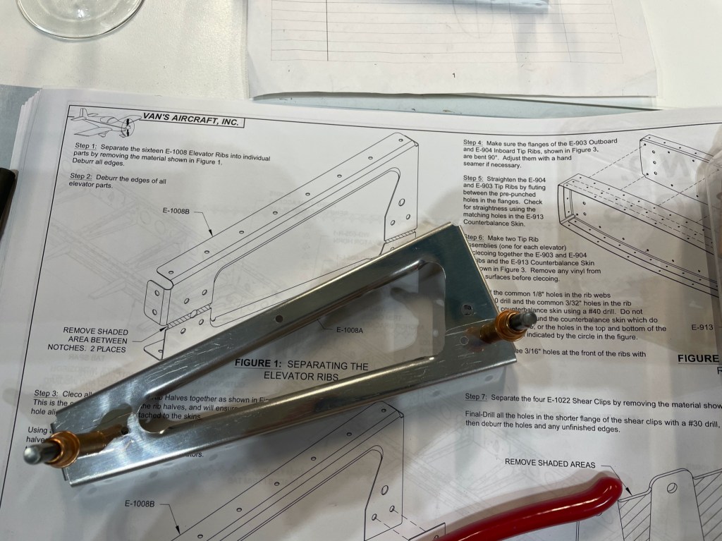
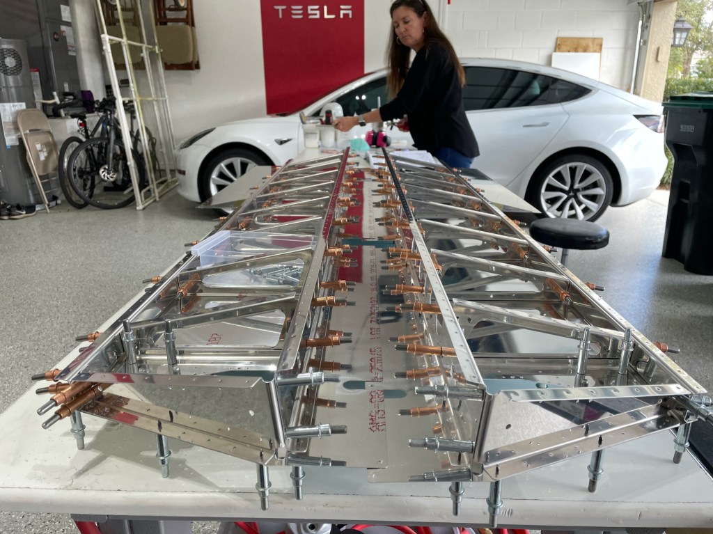
The elevator looks to be somewhat tricky. This is a moveable control surface with a trim tab attached making it the most complex part to date. There are a ton of ribs in this.

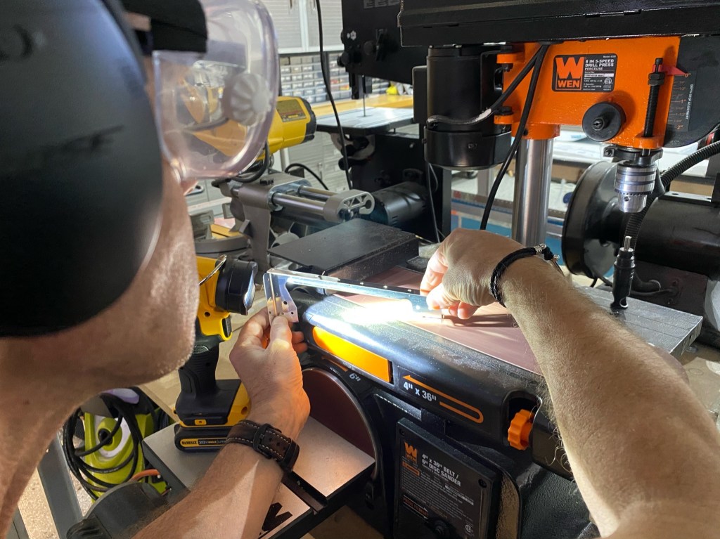
Each rib is actually cut down from a stamping at the factory and then re-attached with rivets when complete. Lots of de-burring here. The band saw makes some pretty deep gouges in the aluminum which all need to be sanded or buffed out.
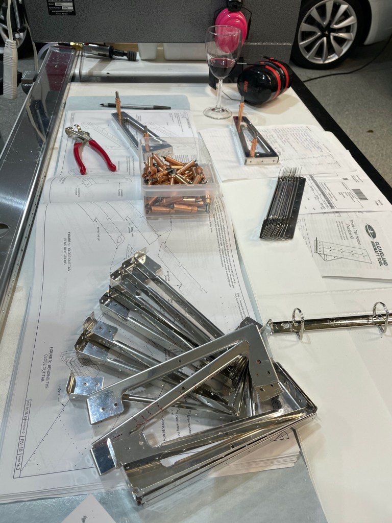
You can see that these start as a single unit but are clecoed together and eventually riveted back together.
The counterbalance ribs came pre-formed, This aluminum is much thicker than anything we’ve used so far. I suspect that is due to the additional strength necessary since the counterbalance protrudes out into the slipstream.
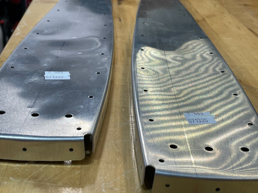
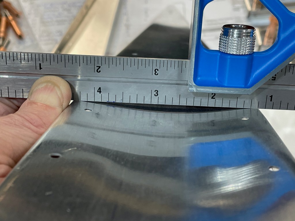
Due to the manufacturing process some of the metal needed to be formed a bit.
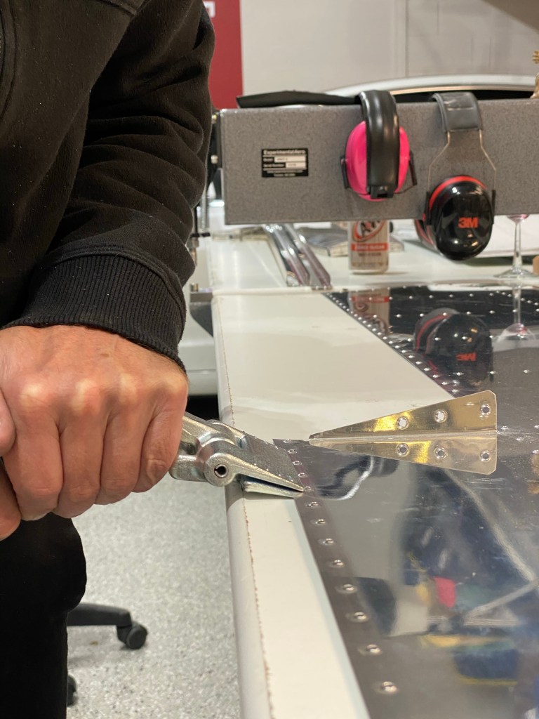
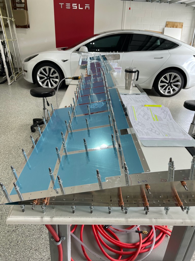
The always pleasant “removing of the vinyl”! It’s a very tedious job but it really protects the aluminum during the building process.
Clecoing the substructure together.
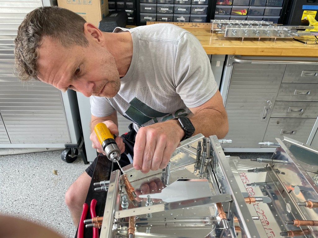
These parts came “final sized” in most cases with very few holes needing to be drilled. Here is a small gusset that connects the root rib and the rear spar that needed to the holes to be final sized. There will be a lot of twisting force in this area as this translates the elevator forces laterally down the elevator.
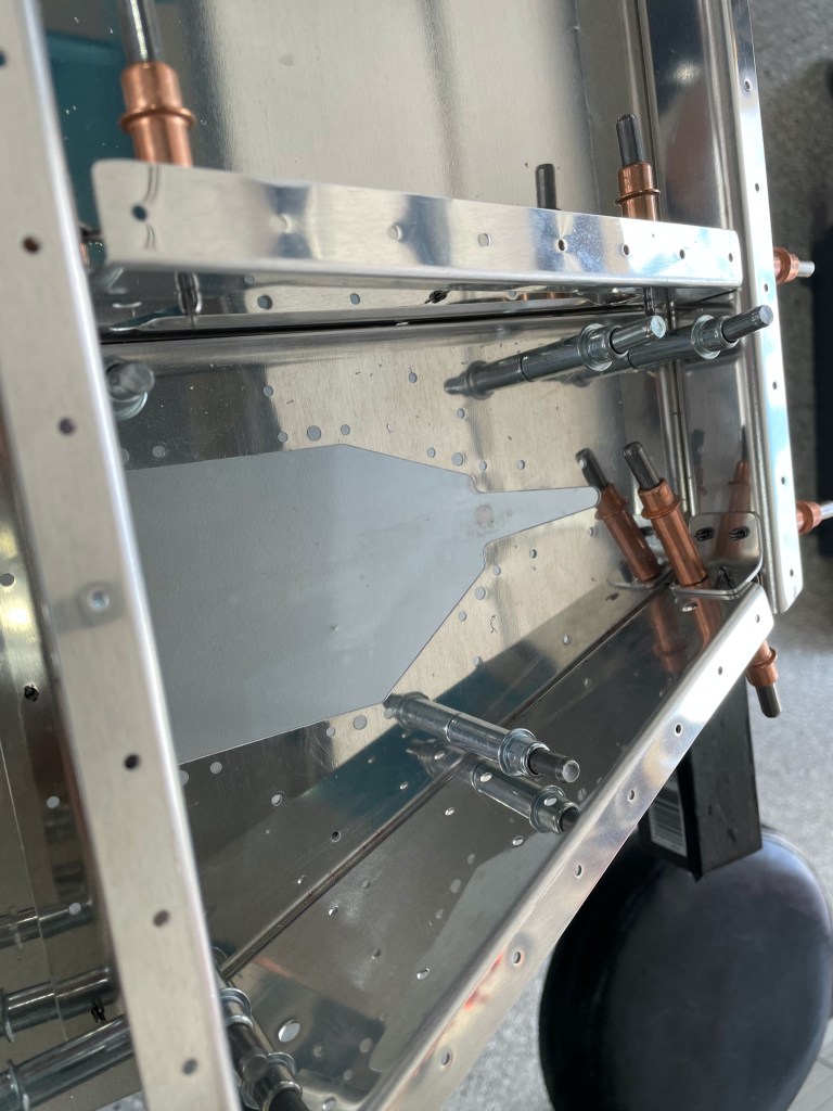
The elevator trim motor sits in here and needs to be reinforced with this plate. It covers the entire bottom of the skin in this area and contains an access panel that is removable from below. There will be several nut plates attached to this plate.
With the substructure complete we installed the top skin in preparation for final drilling. Very few holes need to be final drilled but every single hole was checked just to be sure. The only area that actually need to be final drilled was the counterbalance skin where it sits under the top skin as there are 3 layers of metal that need to be aligned.
Once again we are on to dimpling. The plans don’t make it clear but you do not want to dimple the skins where the fairing will attach. Ultimately these holes will be dimpled but only after fitting the tip fairing and final drilling.
The trailing edge of the rear spar has a trim tab on half of it. The hinge goes underneath the spar flange and the skin on top of the flange. This puts the flange in a sandwich between. The means dimpling the flange in this area is not possible as dimple would protrude down below the spar and interfere with the hinge which needs to sit flat.
The metal on the front and rear spars of the elevator flanges are only 0.032 thick. This is right on the edge of where you could either countersink or dimple. From 0.050 and thicker it’s just too thick to dimple so a counter sink is required.


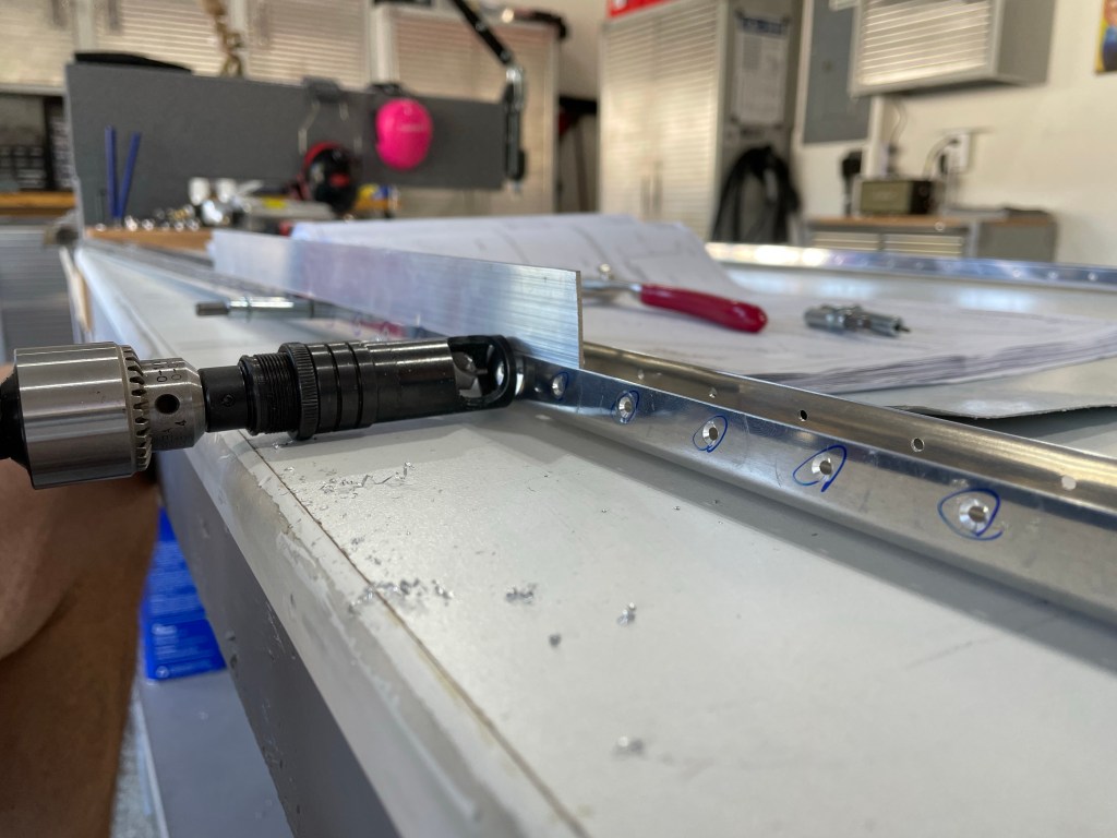
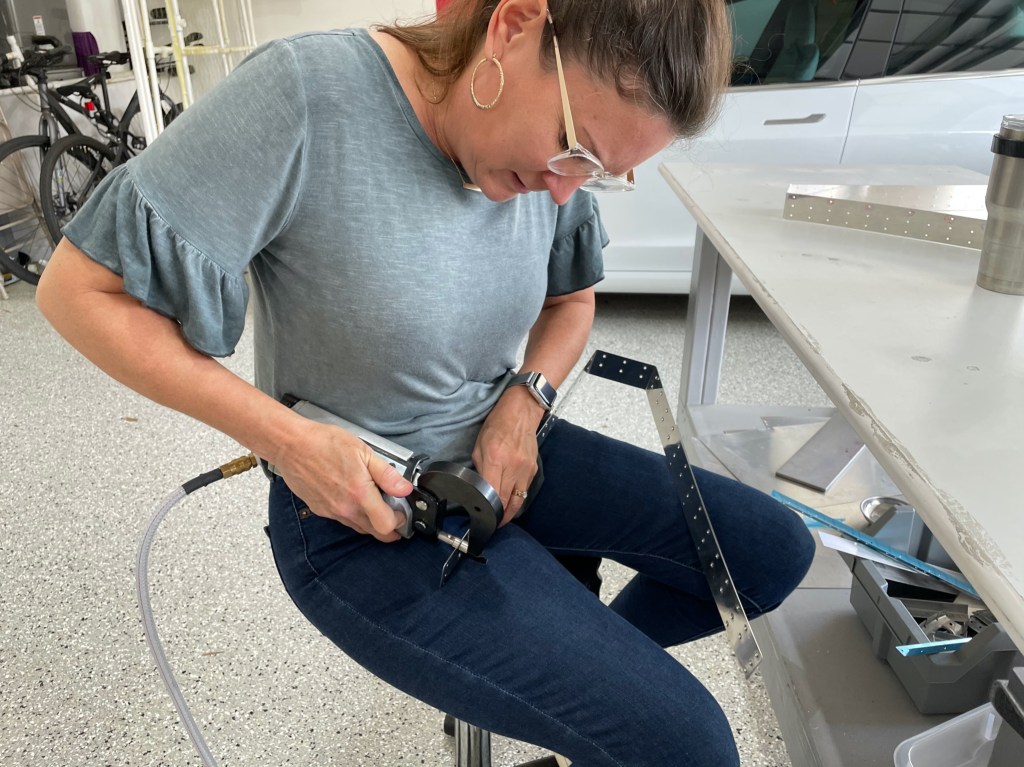
So here we are dimpling the elevator front spar to accommodate 3/32 rivets in 0.032 aluminum.

Tttt